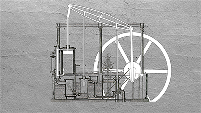
Identifier |
Component |
Description |
1, 2 |
Alternating steam channels |
Directs steam alternately into the cylinder |
A, B |
Slide valves |
Regulate steam supply |
C |
Spray nozzle |
Atomizes cooling water in the condenser |
D |
Water valve (condenser → vacuum pump) |
Controls water flow between condenser and pump |
E |
Water valve (vacuum pump → reservoir) |
Regulates discharged water |
F |
Feed pipe |
Delivers water to the boiler |
G |
Cooling water suction pipe |
Draws water for condenser cooling |
H |
Steam cylinder with steam jacket |
Main cylinder where the piston operates |
uu |
Control box |
Regulates steam intake and exhaust |
K |
Exhaust steam condenser |
Cools and condenses used steam |
L |
Air pump (vacuum pump) |
Creates vacuum in the condenser |
M |
Feed pump |
Supplies water to the boiler |
N |
Governor drive shaft |
Connects the governor to the machine |
O-x |
Crank |
Converts piston motion into rotation |
P |
Cooling water inflow |
Supplies cooling water to the condenser |
S |
Excenter |
Controls valve motion |
R |
Governor drive |
Transmits motion to the governor |
T |
Governor drive belt |
Drives the governor via pulley |
U |
Flywheel |
Stores energy for smooth operation |
W |
Throttle valve |
Regulates steam intake |
Z |
Double-acting piston |
Driven by steam on both sides |
a-b-c-d-e |
Beam |
Balances piston motion |
d-d’ |
Cooling water pump linkage |
Operates the cooling water pump |
e-x |
Connecting rod |
Transfers piston force to flywheel |
f |
Piston rod |
Connects piston to beam |
g-h-k, g’-h’-k’ |
Governor linkage |
Transfers motion to the governor |
k-l-m-n-o-y |
Governor-throttle linkage |
Adjusts throttle valve via governor |
i |
Governor weights |
Adjust rotational speed regulation |